BGP For Boneheads
 Today we’ll go over a quick BGP lab environment using four virtual Cisco CSR1000V routers (IOS-XE based) and a pair of Linux end hosts. I’ll try to explain the configuration as best I can but you should know that I have no idea what I’m doing. This lab is the result of numerous Google searches and a beer or two. Or six.
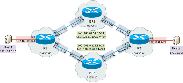
Above is the topology for my lab environment. I wanted to simulate two end clients both peering to a pair of ISPs. I used /24’s for the “inside” network for each client and /30’s for BGP connectivity. I also threw some loopback addresses on the ISP routers based on RFC 6598/2544/5737 reserved blocks so the routing table wouldn’t be empty.
With the previously seen topology, here is what a trace looks like between the two end hosts:


Both directions are passing through the ISP1 router. What I did next is a hard BGP reset on ISP1 using clear ip bgp * so the sessions would briefly drop. Our path between the two end hosts now goes over ISP2:


Now I’ll dump the configs of the four routers and explain why I used what I did.
! R1
router bgp 65400
 bgp log-neighbor-changes
 bgp dampening
 network 192.168.0.0 mask 255.255.0.0
 neighbor ISP1 peer-group
 neighbor ISP1 remote-as 65410
 neighbor ISP1 version 4
 neighbor ISP1 soft-reconfiguration inbound
 neighbor ISP1 prefix-list OUTBOUND out
 neighbor ISP2 peer-group
 neighbor ISP2 remote-as 65420
 neighbor ISP2 version 4
 neighbor ISP2 soft-reconfiguration inbound
 neighbor ISP2 prefix-list OUTBOUND out
 neighbor 10.1.1.1 peer-group ISP1
 neighbor 10.2.2.1 peer-group ISP2
ip route 192.168.0.0 255.255.0.0 Null0
ip prefix-list OUTBOUND seq 5 permit 192.168.0.0/16 le 32

! R2
router bgp 65401
 bgp log-neighbor-changes
 bgp dampening
 network 172.16.0.0 mask 255.255.255.0
 network 172.16.1.0 mask 255.255.255.0
 neighbor ISP1 peer-group
 neighbor ISP1 remote-as 65410
 neighbor ISP1 version 4
 neighbor ISP1 soft-reconfiguration inbound
 neighbor ISP1 prefix-list OUTBOUND out
 neighbor ISP2 peer-group
 neighbor ISP2 remote-as 65420
 neighbor ISP2 version 4
 neighbor ISP2 soft-reconfiguration inbound
 neighbor ISP2 prefix-list OUTBOUND out
 neighbor 10.3.3.1 peer-group ISP1
 neighbor 10.4.4.1 peer-group ISP2
ip route 172.16.0.0 255.255.255.0 Null0
ip route 172.16.1.0 255.255.255.0 Null0
ip prefix-list OUTBOUND seq 5 permit 172.16.0.0/24 le 32
ip prefix-list OUTBOUND seq 10 permit 172.16.1.0/24 le 32

! ISP1
router bgp 65410
 bgp log-neighbor-changes
 bgp dampening
 redistribute connected
 neighbor R1 peer-group
 neighbor R1 remote-as 65400
 neighbor R1 version 4
 neighbor R1 soft-reconfiguration inbound
 neighbor R1 prefix-list IN-FROM-CLIENT in
 neighbor R2 peer-group
 neighbor R2 remote-as 65401
 neighbor R2 version 4
 neighbor R2 soft-reconfiguration inbound
 neighbor R2 prefix-list IN-FROM-CLIENT2 in
 neighbor 10.1.1.2 peer-group R1
 neighbor 10.3.3.2 peer-group R2
 distribute-list prefix NOPE out
ip prefix-list IN-FROM-CLIENT seq 5 permit 192.168.0.0/16 le 32
ip prefix-list IN-FROM-CLIENT2 seq 5 permit 172.16.0.0/24 le 32
ip prefix-list IN-FROM-CLIENT2 seq 10 permit 172.16.1.0/24 le 32
ip prefix-list NOPE seq 5 deny 10.0.0.0/8 le 32
ip prefix-list NOPE seq 20 permit 0.0.0.0/0 le 32

! ISP2
router bgp 65420
 bgp log-neighbor-changes
 bgp dampening
 redistribute connected
 neighbor R1 peer-group
 neighbor R1 remote-as 65400
 neighbor R1 version 4
 neighbor R1 soft-reconfiguration inbound
 neighbor R1 prefix-list IN-FROM-CLIENT in
 neighbor R2 peer-group
 neighbor R2 remote-as 65401
 neighbor R2 version 4
 neighbor R2 soft-reconfiguration inbound
 neighbor R2 prefix-list IN-FROM-CLIENT2 in
 neighbor 10.2.2.2 peer-group R1
 neighbor 10.4.4.2 peer-group R2
 distribute-list prefix NOPE out
ip prefix-list IN-FROM-CLIENT seq 5 permit 192.168.0.0/16 le 32
ip prefix-list IN-FROM-CLIENT2 seq 5 permit 172.16.0.0/24 le 32
ip prefix-list IN-FROM-CLIENT2 seq 10 permit 172.16.1.0/24 le 32
ip prefix-list NOPE seq 5 deny 10.0.0.0/8 le 32
ip prefix-list NOPE seq 20 permit 0.0.0.0/0 le 32
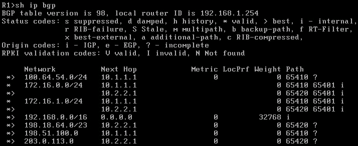
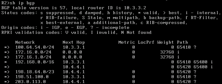
On R1 I advertised the prefix 192.168.0.0/16 though as you saw in the topology we only actually used a /24. On R2 I advertised two /24s with one going to the end host and another actually attached to a loopback interface. For the neighbor configuration on all routers I used peer groups to make it a little easier to read. I also used prefix-list for the outbound routes on the client routers and for the inbound routes on the ISP routers. On the ISP routers I set it to redistribute connected interfaces so I could get the loopback subnets in the routing table, but this also redistributed the /30 links to both client routers. To get around this I created the NOPE prefix-list denying 10.0.0.0/8 and used distribute-list prefix NOPE out on each ISP router. Below you can see the BGP routes on each client router:
So there you have it. Possibly at some point in the future I’ll revisit this with route maps, community strings, neighbor weight and influencing routing paths but as previously stated I have no idea what I’m doing. This was simply an experiment to see if I could…

