
Cisco 1941W and AP801 Basics (Part 1)
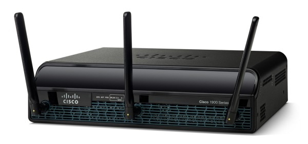
I recently saved a Cisco 1941W Integrated Services Router from a recycling pile for the purpose of adding another IOS 15.x capable device to my home lab stack, but as this device also has an AP801 wireless module I may end up replacing some of my own consumer grade wireless junk at home with this router. This is part 1 of (hopefully) a collection of articles I’ll be writing as I make progress in this project.
My hardware configuration included 512MB onboard memory and a 256MB Compact Flash card. When I watched the console messages during boot I noticed that it referenced an empty DIMM slot. Curious about this I pulled the cover off and installed a 1GB stick of DDR2 non-ECC (ECC will halt booting) memory. Next power-on it read my upgrade and showed a total of 1.5GB memory installed. This is probably pointless for most home applications but I have bins of old garbage hardware so this didn’t cost me anything to do.
Resetting Passwords/Configs
Getting full access to the 1941W itself is a fairly standard process similar to most other Cisco devices I’ve messed with in my lab. During the power-on process, send a break command through your serial console until you reach the ROMMON mode. An alternative method appears to be removing the Compact Flash boot card and powering up the router. Once in ROMMON, issue the command “confreg 0x2142” and reload the router.
When the router completes the reload config, it should drop you into a standard router prompt with none of the original startup config applied. Assuming you don’t plan on keeping some random person’s router config, I usually just write the running config to flash to overwrite all existing settings. From the config mode, do “config-register 0x2102” to prevent the router from booting into a default config again. Do a reload at this point just to make sure your console takes you into the expected router prompt without a password.
Upgrading IOS Image
My router had a fairly old image somewhere around IOS 15.1 and appeared to have a build date in 2012. I wanted to get something more modern with whatever new features and security improvements Cisco has made over the years, so I obtained IOS image c1900-universalk9-mz.SPA.157-3.M5.bin to load in. If you don’t want to try loading IOS images over your console session, your best bet is to get your router on your internal network. I ran a cable from GigabitEthernet0/0 to my home network (flat design, no VLANs) and assigned a free IP to it:
interface GigabitEthernet0/0
  ip address 192.168.0.10 255.255.255.0
I found an easy way to get IOS images to a router is to have a Linux VM on my home network with different protocols such as HTTP/FTP/TFTP. My original IOS image was able to do HTTP and FTP so that did make things easy. First up you should probably verify you’ve got enough flash space available:
c1941# dir /all
Directory of flash0:/

9 -rw- 85064020 Dec 17 2019 06:57:44 +00:00 c1900-universalk9-mz.SPA.157-3.M5.bin
10 -rw- 75551300 Jul 12 2015 06:31:48 +00:00 c1900-universalk9-mz.SPA.154-3.M2.bin

256487424 bytes total (90607616 bytes free)
Sometimes users like to leave old images behind during upgrades. To get my desired image into flash, I basically just ran “copy http: flash0:” and specified the IP of my web server and IOS image name to download. Keep in mind we never defined a default route so if your IOS image is located outside of your directly connected network, you’ll need to configure a route accordingly.
Once the IOS image is in flash, configure the router to use it for boot:
c1941(config)#boot system flash0 c1900-universalk9-mz.SPA.157-3.M5.bin
c1941(config)#do wr
Building configuration...
[OK]
Reload your router and you should be running the new image.
c1941#sh ver
Cisco IOS Software, C1900 Software (C1900-UNIVERSALK9-M), Version 15.7(3)M5, RELEASE SOFTWARE (fc1)
Technical Support: http://www.cisco.com/techsupport
Copyright (c) 1986-2019 by Cisco Systems, Inc.
Compiled Thu 26-Sep-19 23:54 by prod_rel_team

ROM: System Bootstrap, Version 15.0(1r)M15, RELEASE SOFTWARE (fc1)
System image file is "flash0:c1900-universalk9-mz.SPA.157-3.M5.bin"
Once the new image is running I usually like to perform another write config to flash operation in case the running config has any changes from the new image.
Basic Setup Options
Now that you’ve got your desired IOS image, we should configure some basic necessities.
c1941(config)#service password-encryption
c1941(config)#ip domain-name home.lab
c1941(config)#no ip domain-lookup
c1941(config)#crypto key generate rsa
c1941(config)#username admin privilege 15 password (your password here)
c1941(config)#enable password (your password here)
c1941(config)#ip ssh version 2
c1941(config)#line vty 0 4
c1941(config-line)#login local
c1941(config-line)#transport input ssh
The above should get some basic local authentication going and enable SSH sessions to the IP you previously configured on gi0/0.
Next up we’re going to create some basic networking to help us interact with the AP801 module inside the router. I believe the AP802 uses some sort of dual purpose image on the main router flash but my AP801 has its own boot image within its own flash media, and you need to get the internal bridge going in order to transfer data between the router and the AP801.
interface Vlan1
  ip address 10.10.0.1 255.255.255.0
ip dhcp pool embedded-ap-pool
  network 10.10.0.0 255.255.255.0
  default-router 10.10.0.1
interface wlan-ap0
  ip address 10.30.0.1 255.255.255.0
interface Wlan-GigabitEthernet0/0
  switchport mode access
  no ip address
Reviewing the above portion from my router’s config, we need to create an IP address on the default VLAN interface 1. This is then used to create a DHCP pool which the AP801 will assign an IP from to create the internal bridge. The wlan-ap0 interface is the direct connection to the service module and you need to assign a random unused IP address to this interface in order to establish a console session. The final interface “Wlan-GigabitEthernet0/0” is the network bridge between the 1941W and the AP801. Make sure that interface is in access mode and has no IP assigned. Default VLAN 1 should apply to the interface without needing to specify it. Before we continue, make sure the “wlan” related interfaces are up and not in admin down state.
Configuring The AP801
This part was fairly new to me so after using the service-module command to open a console to the AP801, I found out that it requires its own set of login credentials which I did not have. Like we did to the main router at the start of this article, I’m going to reset the AP801 to the default configuration. This is actually pretty simple assuming your router supports this command syntax:
c1941#service-module wlan-ap0 reset default-config
If this is not available, you might need to have a console session already established and attempting to send a break command during a reload of the AP801. After performing the above command, this is how you establish a console session to the module:
c1941#service-module wlan-ap0 session
Trying 10.30.0.1, 2067 ... Open
User Access Verification
Username: cisco
Password: cisco
ap#
As seen above, the default login and password should drop you directly into an enable mode prompt in the AP801. When doing a “sh ver” I found that my AP boot image was version 12.4 and I really wanted something newer, so I needed to get the AP module talking to my router’s network to allow for downloading of a new boot image. The default configuration should have MOST of what we need already in place, but you’ll need to do the following:
interface BVI1
  ip address dhcp client-id GigabitEthernet0
  (or simply ip address dhcp)
If you check GigabitEthernet0 you should see it already part of bridge-group 1. By telling BVI1 to address itself via DHCP, it should pull an IP from the 1941’s previously configured pool. The end result is you should be able to ping the vlan1 IP of the 1941 from the AP801:
ap#ping 10.10.0.1
Type escape sequence to abort.
Sending 5, 100-byte ICMP Echos to 10.10.0.1, timeout is 2 seconds:
!!!!!
Success rate is 100 percent (5/5), round-trip min/avg/max = 1/202/1000 ms
ap#sh ip arp
Protocol Address Age (min) Hardware Addr Type Interface
Internet 10.10.0.1    0    fc99.xxxx.xxxx  ARPA  BVI1
Internet 10.10.0.3    -    70ca.xxxx.xxxx  ARPA  BVI1
While this was neat and all, I couldn’t make it access the same Linux VM with my Cisco images as I previously used so I decided to use a different way for getting a newer AP boot image installed.
Upgrading AP801 Boot Image
According to the Cisco download area, the latest autonomous AP IOS image for the AP801 module is ap801-k9w7-tar.152-2.JA1.tar. In order to get this archive extracted to the AP801 flash, I’ll first download a copy of it to my 1941’s flash via HTTP and then enable a TFTP server on the 1941:
c1941(config)#tftp-server flash0:/ap801-k9w7-tar.152-2.JA1.tar
Jump back into the AP801 console and check the disk space on the flash storage. In my case I had to delete the image directory of the running software due to lack of space. Keep in mind we need enough space for the tar archive and to extract it. Using the previously configured bridge network, I downloaded the new software over TFTP and extracted the files:
ap#copy tftp: flash:
Address or name of remote host []? 10.10.0.1
Source filename []? /ap801-k9w7-tar.152-2.JA1.tar
Destination filename [ap801-k9w7-tar.152-2.JA1.tar]?
Accessing tftp://10.10.0.1//ap801-k9w7-tar.152-2.JA1.tar...
Loading /ap801-k9w7-tar.152-2.JA1.tar from 10.10.0.1 (via BVI1): !!!!!!!!!!!!!!!!!!!!!!!!!!!!!!!!!!!!!
[OK - 9236480 bytes]
9236480 bytes copied in 106.388 secs (86819 bytes/sec)

ap#archive tar /xtract ap801-k9w7-tar.152-2.JA1.tar flash:
extracting info (279 bytes)
ap801-k9w7-mx.152-2.JA1/ (directory)
extracting ap801-k9w7-mx.152-2.JA1/ap801-k9w7-mx.152-2.JA1 (8250824 bytes)
...etc etc
Now that the new image is ready to go, we have to reset the AP801 into the bootloader for further configuration, as the location of the boot image is not part of the running config like the 1941. From the 1941, perform this reset:
c1941#service-module wlan-ap0 reset bootloader
Re-establish a console session to the AP801 if you don’t already have this going in another window. You should end up in the “ap:” bootloader prompt. We will check and change the boot settings below:
ap: set
BOOT_AUTO_MODE=flash:/ap801-k9w7-mx.124-21a.JA1/ap801-k9w7-mx.124-21a.JA1

ap: set BOOT_AUTO_MODE flash:/ap801-k9w7-mx.152-2.JA1/ap801-k9w7-mx.152-2.JA1

ap: set BOOT flash:/ap801-k9w7-mx.152-2.JA1/ap801-k9w7-mx.152-2.JA1

ap: reset
Are you sure you want to reset the system (y/n)?y
System resetting...
I’m not sure how important the BOOT_AUTO_MODE line is or if it updates itself automatically next boot, but make sure you set BOOT with the same image or it’ll resort to booting into the emergency recovery image assuming you still have one in your flash storage.
ap#sh ver
Cisco IOS Software, AP801 Software (AP801-K9W7-M), Version 15.2(2)JA1, RELEASE SOFTWARE (fc1)
Technical Support: http://www.cisco.com/techsupport
Copyright (c) 1986-2013 by Cisco Systems, Inc.
Compiled Wed 23-Jan-13 15:07 by prod_rel_team

ROM: Bootstrap program is AP801 boot loader
BOOTLDR: AP801 Boot Loader (AP801-BOOT-M) Version 12.4(23c)JX, RELEASE SOFTWARE (fc1)
System image file is "flash:/ap801-k9w7-mx.152-2.JA1/ap801-k9w7-mx.152-2.JA1"
Everything seems to be as expected. Something I did notice though is you can actually find what appears to be a newer image “ap801-k9w7-tar.152-4.JA1.tar” under a different product download area on Cisco’s site and this also seemingly works. These are still pretty old and I don’t know if anything newer was ever out for this platform.
This will wrap up part 1 of this article series. In the next entry, I hope to investigate creating wireless networks and other fun.


Did you do any more parts to the article?
I have same upgrade to do. Also for the last week spent a lot and I mean a lot of time configuring this AP with multiple vlans. Finally got it going. Tomorrow my new firewall hardware comes and plan to use this with the 1941W for home network and lab. Thanks – good article.
Unfortunately I haven’t gotten around to doing further work on it. My planned part 2 was going to include using the router as a wireless bridge to receive a signal from another router but I’m not sure the system actually supports that.